TD Clock Transistor Circuit, Construction Notes
Tim Wilkinson
The aim of this conversion is to improve the lifetime of the T-type clock by
eliminating sparking of
the electrical contacts. Note that for this to work, the basic clock mechanism
needs to be in sound
condition and appropriate care needs to be taken to avoid any damage to the
delicate components. If
either is not the case you could be better off trying to find a professional
restorer.
To complete the transistor conversion you’ll need at least the appropriate
electronic components, a
low-power, fine-tipped soldering iron, some fine rosin-core solder, and
reasonable electronic
soldering skills (along with some luck regarding the original condition of your
clock).
You may find you have ultimately to clean, adjust and lubricate the clock as
outlined in the references
below to get it going properly, although I haven’t found this necessary so far.
Preparation
By far the best approach is to get the basic clock running before applying the
conversion. This could
require gentle cleaning with fine abrasive and alignment of the pivoting contact
and balance wheel
pin. If the clock hasn’t had attention recently you may also need to lubricate
the clock mechanism to
get it running, applying tiny quantities of light machine oil to at least the
balance wheel mounting and
adjacent components, including the pivoting contact mechanism.
If this doesn’t do the job, the next step would be to check the electrical
continuity of the coil
(probably around 600 ohms). The external leads have delicate connections with
the coil winding,
which may have become detached through mishandling. If so, it will be a delicate
job to remove the
coil and its insulation and repair the connection. I have found repairing the
coil bobbin and/or
windings is also possible, but this requires more disassembly of the clock, a
quantity of the very fine
gauge insulated coil wire (apparently available only on large spools), and some
kind of coil winder.
Schematic
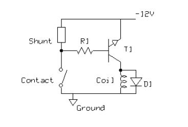
The suggested transistor circuit design is shown in the schematic below. The
only new components
needed are the transistor T1, resistor R1 and diode D1, which are added to the
existing clock electrical
components as shown. R1 controls the minimal base current through the contact
and T1, which then
switches the coil current. D1 serves to protect the transistor from reverse
voltage spikes generated by
the coil. The shunt is a ballast resistor originally used as a basic form of
spark reduction. It can be left
in place.
T1 is a general purpose silicon NPN transistor in a plastic TO92 package, BC547C
or similar (e.g.
BC550C). (Pin designations can be viewed on the relevant datasheet available
online.)
R1 is a 10 kOhm, 0.25W carbon resistor.
D1 is a minimum 50V, 1A rectifier diode (e.g.1N4001 through 1N4007).
Circuit layout
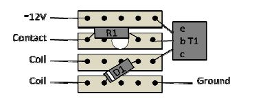
There are a number of ways you could construct the circuit. I tend to use ‘stripboard’
prototyping
board (e.g. Veroboard), which consists of copper strips with holes on a 0.1 in
pitch laminated on a
resin board. The layout below uses this technique and is designed to be compact
enough to fit snugly
between the coil and clock base, if you take care to lay the components flat,
restrict the height of all
soldered joints (if necessary by filing down) and turn the transistor on its
side next to the board as
shown. The cut through the strip under R1 can be done using a drill bit or sharp
knife.
Normal precautions must naturally be taken to avoid damage when soldering the
leads of the
electronic components, using a heat sink if necessary to avoid thermal damage.
Car must also be taken
to eliminate any possibility of solder bridging between the strips.
To complete the conversion, the existing single strand wire connections from the
coil will need to be
gently unsoldered (carefully avoiding stress at the coil) and re-soldered to the
stripboard as shown.
These connections are polarity insensitive. The remaining connections can be
made to the -12v supply
and the contact terminal using fine, preferably multi-strand, flexible insulated
wires. The circuit
ground wire needs to be spread and wrapped under one of the clock’s brass posts,
or otherwise
connected to the clock ground.
As with much of the car’s electrical system, it’s much safer to carry out
initial testing using a power
supply such as a battery charger rather than the car battery.
With some luck, you’ll have the satisfaction of seeing and hearing your clock
happily ticking once
again.
Adapting for negative ground
I haven’t actually built one of these, but it should be fairly easy to adapt the
above design to
accommodate cars which have been converted to negative ground. In this case the
clock power supply
will now obviously be +12V in the above diagrams. Other design changes are
suggested simply as
follows:
- For T1 use an equivalent PNP transistor such as BC557C or similar (e.g.
BC560C). (For PNP
transistors the emitter arrowhead is reversed.)
- Reverse diode D1
In other respects the implementation should be able to remain unchanged.
References
1. Cleaning the T-Series Clock, Blake Urban, TSO issue 4, 2002 (also at
www.angelfire/alt/yd3/TD/clock.htm)
2. The Clock, A Definitive Description, Hal Kramer, TSO issue 6, 1992
3. More On Clocks, John Marks, TSO issue 10, 1992
4. The Electric Clock, Brian Hough, http://mg-tabc.org/techn-up/electrical_clock.htm
This document was created with Win2PDF available at http://www.win2pdf.com.
The unregistered version of Win2PDF is for evaluation or non-commercial use
only.
This page will not be added after purchasing Win2PDF.