This article is about my success at
installing a Dynamator alternator into Lazarus, my 1952 TD 10855.
Lazarus has been converted to a negative ground configuration as
long as I've had him. Being a retired EE, I'm just to much of
an electronic'er to have it any other way. I'll not be getting
into the steps necessary to convert from a positive ground
configuration to negative ground. A bit of background. If you follow the
train from
Alternators for Tcars
you'll see how I got into the alternator world. In the past
month I ran into some problems with Lazarus' charging system that
led me to believe that I had either a bad dynamo or battery, or
both. Three control boxes (voltage regulators) weren't solving
the problem. I decided to bite the bullet and try an
alternator. Abingdon Spares has recently begun carrying a line
of U.K.-built alternators called Dynamators at a very reasonable
price, ~$220US. For the past month I've been doing a lot of
corresponding with Mort Resnicoff and Jim Northrup about Mort's
problems with his Dynamator. So I've picked up quite a bit
info about them. A bunch of Googling led me to suspect that
the trick necessary to convert a negative ground TD from dynamo to
Dynamator was to KISS (Keep It Simple Stupid). I saw two
approaches - one was the Stealth approach for an installation where
the casual observer wouldn't see the difference. That meant
having to sacrifice a control box by gutting its contents. The
other approach was to simply apply a standard electrical wiring
connection strip. I had an old RB106/2 control box that had
seen better days, so I started down that path. Here's what the
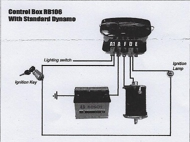
Dynamator folks put into the package:
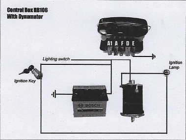
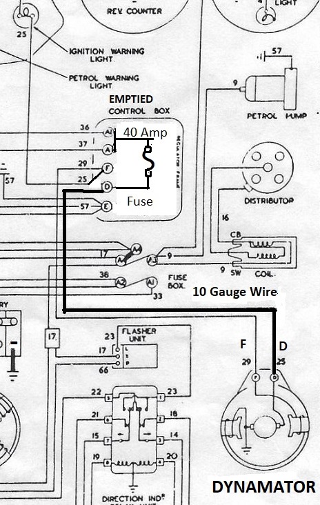
Notice that the 'With Dynamator' shows
nothing connected to the RB106 except a ground wire on terminal E.
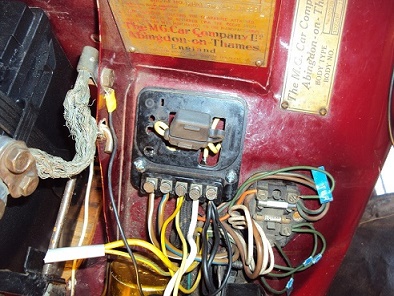
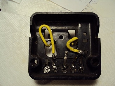
The control box must be totally eviscerated for this application. The device in the empty control box is a 40
amp fuse. What does all of this accomplish? Here: The wires attached to A1 and A of the control
box are bussed together and the 40 amp fuse is connected to them.
The other end of the fuse is connected to the D terminal. The
small yellow wire from the Ignition Warning Light that was attached
to the D terminal is now connected to the F terminal with the Field
wire from the Dynamator. The black (ground) wires remain
connected to the E terminal. I have connected the D terminal
of the control unit to the D terminal of the Dynamator with a length
of yellow,10 gauge wire. Dynamator says -- Note: The wire used
as main feed from Dynamator to Battery should be rated at at least
45 amps. IMHO, the short length of 10 gauge wire should satisfy that
demand, but the decision is yours. The yellow wire presently
connecting the D terminals is designed to handle the 20 amps of the
C39/C40 dynamo. One might want to change the path of the D
wire since the D terminal is a push-on terminal on the end of the
Dynamator.
It's not mentioned in the instructions, but
you'll need to swap the cooling fan from your dynamo to the
Dynamator. When I first ran my engine I could hear the
ping-ping of the fan contacting the Dynamator housing. I
solved that by installing a thin spacing washer (26 ga. steel) below
the fan. I think that the interference may have been due to the
repro fan that I've had on the dynamo. FYI, the 40 amp fuse
and the 10 gauge wire are readily available at NAPA stores. Next comes the directions for doing the
conversion without the control box.
Click here.
Ttalk.info
Dynamator for Lazarus
Who's Lazarus?